I got bored one Saturday afternoon so decided to fire up the original steam engine I made. Here is some video I took with my iPhone whilst it was running.

gimbalStuff is for people who want to peek inside my shed, and see what I am up to.
Wednesday 16 December 2009
Sunday 6 December 2009
Boiler dissappointment....then success!
The saga of the boiler continues.....
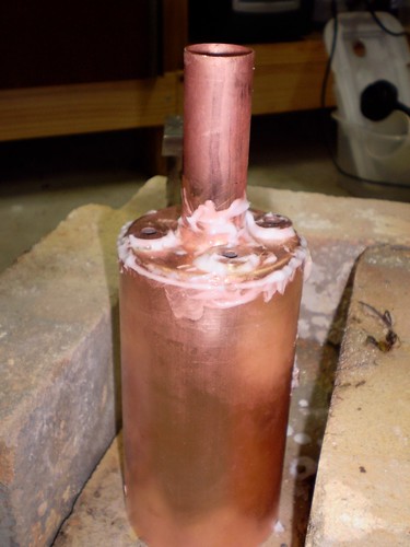
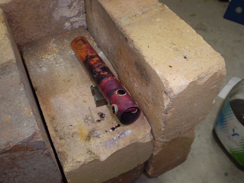
After soldering the top plate on, I find that I missed a bit between the shell and the top plate!! (sorry for the quality of the photo).
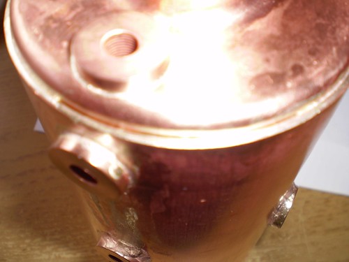
Easy to fix - just more flux and heat and we are ready for hydro testing. Here is the set up; a couple of hours at the lathe gives me a bunch of blanking plugs (where did I put the ones I used last time??). These and the judicious application of teflon tape gives me a good seal. I fill the boiler to the top and put the last plug in. Two strokes of the pump and I am up to over twice working pressure (30 psi).

The pressure holds at just under 80psi for over two hours until I get told to remove all the paraphernalia from the kitchen bench. I call this a successful hydro test. All I have to do now is make all the fittings.....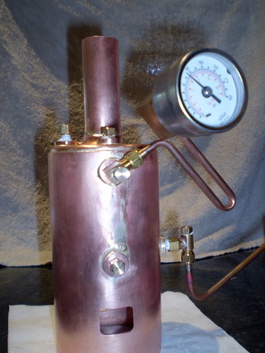
Thursday 3 December 2009
More Boiler Progress (cont)
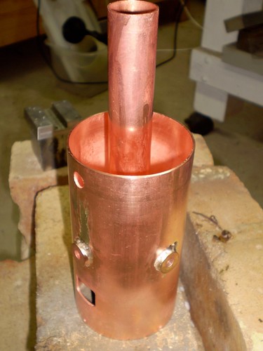
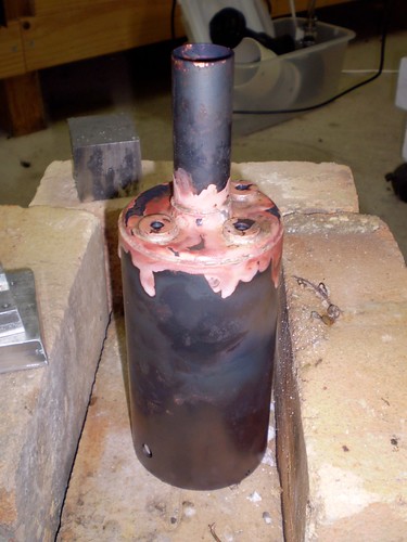
Here are some pic of the latest progress. Here is a shot of the boiler sitting in the hearth after having the bottom tube plate soldered to the shell. The two lower bushings have been soldered in as well. The whole assembly was upside down for this operation and you can see how gravity assisted the distribution of extra silver solder. Better too much than not enough I suppose....
Here is a shot from underneath - nice fillet all the way around so good joints here.
Now we are going to solder the top tube plate on. So liberal with the flux...
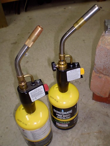
...and apply the heat. I use two MAPP gas torches for this. One has a bigger burner than the other so this gets used for general heating and the other one gets used to supply local heat.
Here we are at black heat still. This will go into the pickle and if there are no visible problems it will be hydro tested.
Saturday 28 November 2009
Forming boiler end plates
I was asked a question recently (at Home Model Engine Machinist) on how the end plates for the boiler currently under construction were formed.
Copper is a malleable material an it annealed state and this means that it can be beaten into shape around a former. During the forming process it work hardens and needs to be annealed again. You can tell when annealing is required because the sound of striking it changes and it stops being easily worked.
Annealing copper in the home shop is pretty easy - I just place it in the hearth (a bunch of fire bricks in the middle of the floor) and heat until dark red hot with a torch. You can leave it to cool in air or quench it - I quench it because I have no patience - the point being that it is the heating that anneals not the way it is cooled.
To shape the copper, you'll need a former; something over which you will hammer the copper. For boiler end plates, I use aluminium. Here are the formers for the 3" vertical boiler fire-tube endplates.

They were turned in the lathe and the diameter is the inside diameter of the boiler shell less twice the thickness of the tube plate. The hole through the middle is calculated in a similar way.
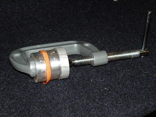
The outer flange is formed by clamping the annealed tube plate between the two formers a beating the copper with a soft faced hammer. Here is is this process illustrated using formers for the end cap of a small butane gas tank. Some people use a vice, but for smaller plates, a substantial G-clamp can be used.
For the central flange in the 3" boiler, the formers and the steel piece you see sitting in the central hole of the rightmost former in the photo above are turned into dies. The plate is formed by forcing the steel piece through gently (I had to stop and anneal a couple of times) using a large vice.
More Boiler Progress
I have another couple of shots of progress on the boiler. The first is the bottom tube plate and the fire-tube after soldering and pickling.
There is a nice fillet of solder at all joints which is what I was aiming for. The citric acid pickle also cleans all the gunk off very effectively such that all that is required is a rub with a scotch brite or wire wool under running water once the job comes out of the bath.
Here is another shot showing the top tube plate with all the bushes soldered in.
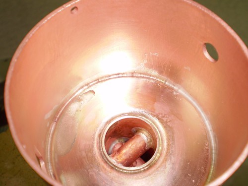
Here is the underside of the top tube plate:

Monday 23 November 2009
A Boiler for the new engine
It's been a while since the last post and now that I have the workshop back up and running again after getting the new lathe and mill operational, I though I would get back to some steam.
I am going to make a steam plant for the new engine so the first thing I need is a boiler. I am going to re-use the design from the last boiler I made, but I am going to skip the superheater and use cross tubes at the bottom of the fire-tube instead. The design is a simple centre flue fire-tube boiler which I will fire with butane gas.
You can see here all the basic bits:
The main shell is 75mm is diameter and the two flanged ends are 1.6mm in thickness (3" and 1/16" respectively for our American cousins). The fire-tube is 25mm in diameter and about 185mm long. The cross tubes are 10mm in diameter and are arranged at 90 degrees across the fire-tube. They have a slight incline so that they are not horizontal. The bushes are bronze (never use brass in a boiler!!) and threaded 1/4"-40 ME.
The first task is to silver solder the cross tubes into the fire-tube.
Here it all is assembled and fluxed, ready for heat. Here is the result after soldering is complete:
This then goes into the citric acid bath I have in the plastic container to pickle overnight. This will remove all the oxidation and mess. It will come out of the bath all clean and ready for the next stage.
Tuesday 29 September 2009
Mounting a DRO on the 6x26 Mill
I kept the chinese DRO scales and readout display from the previous mill. All of the travels were able to accommodate the travels on the new machine. Having a DRO is something I don't think I could now live without.
Here are some photos showing what I did:
I drilled and tapped a couple of M5 holes in the bottom half of the belt guard - this allowed me to attach the readout unit to the side of the machine.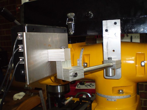
I removed the scale and the stop post that was attached to the front of the table and used the t-nuts that where in the t-slot at the front of the table to attach the X-axis scale. I used some lightweight aluminium angle to protect the scale from chips and coolant etc. The cable was put inside plastic sheathing and was tied down with cable ties.
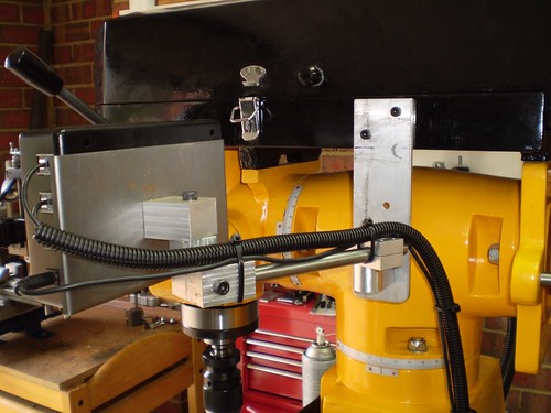
The Y-axis scale was attached to a plate that was attached in turn to the Y-axis stops bracket via standoffs. I used stand offs to clear the oiler for the knee dovetail. I replaced the steel stop piece with a new part that acts as both a stop and a bracket for moving the scale.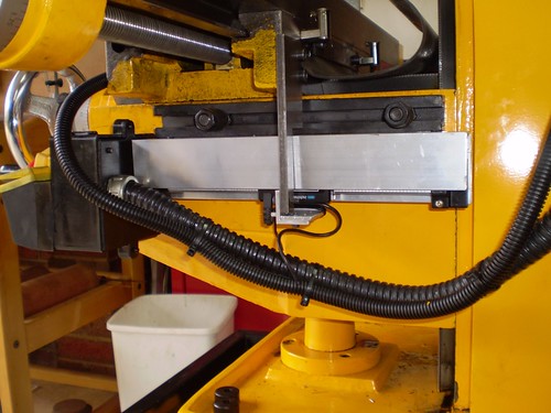
The Z-axis was the only place (aside from the readout bracket) that I had to drill holes to attach the scales. I have not covered these scales yet.
All the cabling was neatly routed and tied down with cable ties.
Tuesday 15 September 2009
A Countershaft for a Taig Lathe
I have been doing a bit of steel turning on the Taig lately again and have been having trouble parting off and form turning. I needed to slow the spindle speed right down. I didn't want to go and spend more money on a DC variable speed drive, plus I don't think they have enough torque at low speeds, so I decided to keep my trusty induction motor. I needed a countershaft.
I wanted a compact design that allowed me to adjust the belt tension easily in both directions and also allowed for quick changes of speeds. I sketched something up.
As you can see from the design, the countershaft is mounted on a pivoting arm that pivots around the same axis as the motor shaft. In this way I can adjust the tension between the motor pulley and the countershaft without disturbing the tension between the lathe and the countershaft. Similarly the tension between the lathe and the countershaft can be adjusted without disturbing the other belt. I also ended up with an assembly that was very compact.

I started to turn sketch into metal.
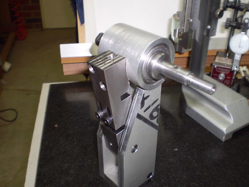
Here you can see the two cheek plates and the pivot arm. The ball bearing are old Taig spindle bearings - bit worn but OK for this job. Here is a shot from the other direction:
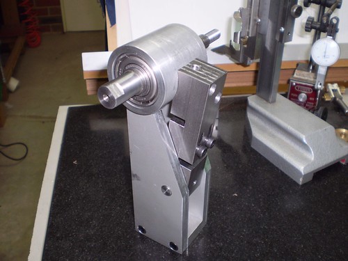
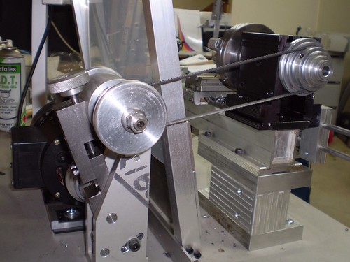
Here is the finished article:
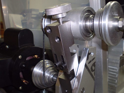
And another close up:
Tuesday 1 September 2009
New Machinery Day!!
It is New Machinery Day!!
I have decided it is time to go bigger - no not like that, I mean upgrade to bigger machinery. To this end my 7x14 minilathe and my X3 mill have been sold on eBay. I got good prices for both so I am pretty happy with the results - they both went to good homes.
I have replaced them with a 250mmx550mm (10x22 to our American cousins) lathe and a 6x26 knee mill. I got these from a local dealer - if you live in Melbourne you can do worse than Standaco in Nunawading.
The crane truck arrived this morning with my goodies on the back. Beautiful day - check out the sky.

Down comes the lathe...
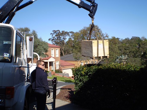
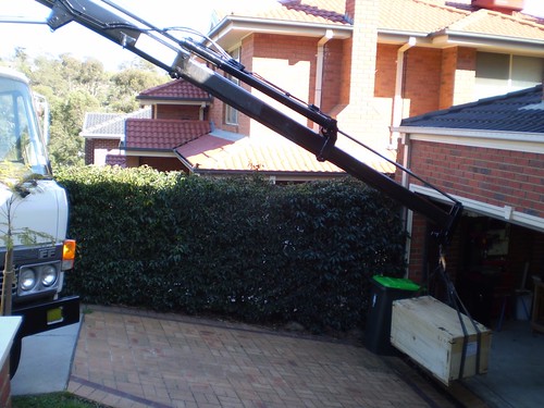
It was much easier than I thought it would be - he basically used the crane jib to lower them straight under the roller door.
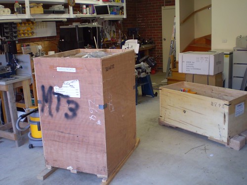
My shop now full of crates to unpack - mill in front, lathe in the middle and their respective stands at the back.
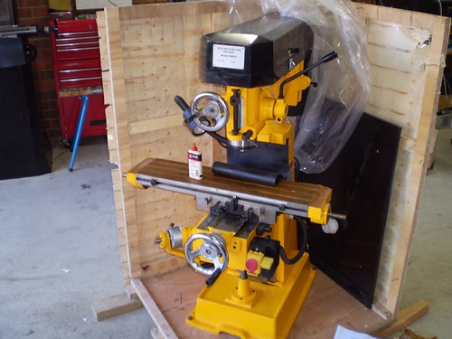
Couldn't resist a small peek before going in to work; the new mill sitting in its crate.
Thursday 23 July 2009
Thursday 25 June 2009
Project - Mine Engine Completed
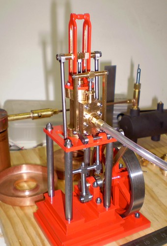
The Mine Engine has been completed!
Sorry the construction series got cut short, however here is the finished product in all its glory. I will upload the remaining drawings I have soon, but wanted to post some photos of the completed article.
Front on shot while running on air. You can see the boiler plates behind as well as the butane gas tank and burner that will eventually fire the boiler.
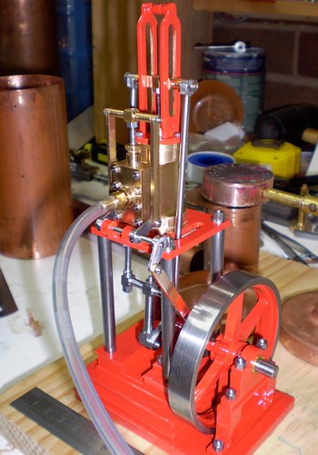
View from other side.
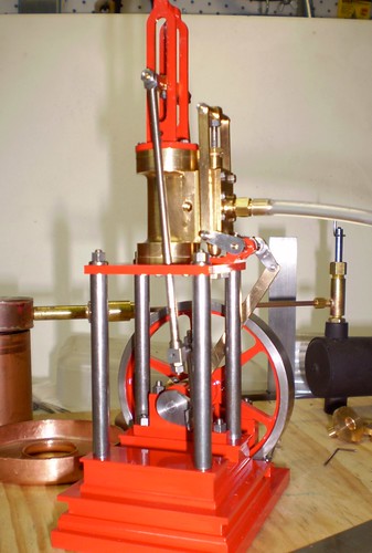
Another view
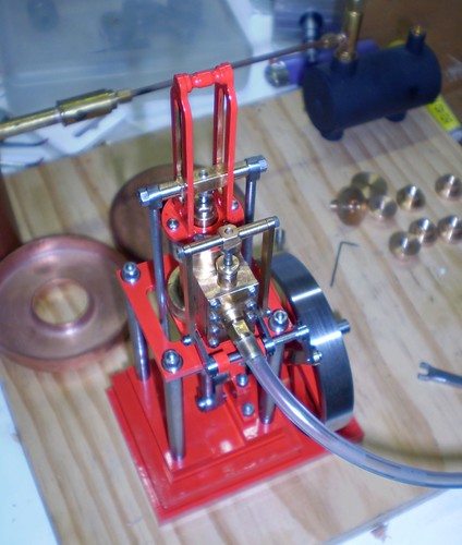
View from the top.
Subscribe to:
Posts (Atom)