Sunday 13 February 2005

Project - Colliery Engine Boiler

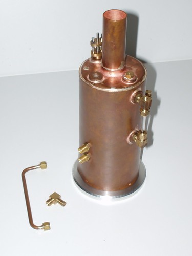
The boiler is 3" drawn copper tube, and is about 6 inches long not including the flue.


The base is aluminium, and it is not complete. Note the oxidation - this boiler has been sitting idle whilst I work on lathe mods for a while and was handled quite extensively. Where it has been handled, it has oxidised.


It will be painted with Hi-Temp black and lagged with hardwood in the end.


http://farm6.static.flickr.com/5140/5540906017_d3bb9470a1.jpg


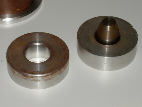
These are the aluminium former and anvil for the two end caps. The small steel piece sitting in the anvil on the right is the drift for forming the flange that mates with the flue.


P2130035 copy


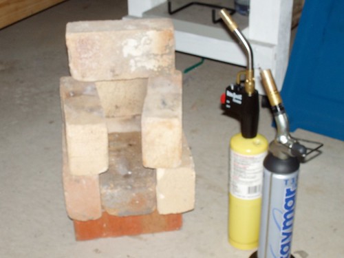
This is a pic of my brazing hearth. :-) A pile of fire bricks that sits on the concreter floor of the shop. Next to it stand the two torches I used to do the soldering on the boiler above.


http://farm6.static.flickr.com/5174/5540906959_649f05bd13.jpg

Thursday 10 February 2005

7x14 Minilathe New Cross/Compound Slide

New cross/compound slide assembly. I was unhappy with the compound slide as it either was bound up solid and wouldn't move or was so loose that surface finish suffered greatly. I decided to make another one and while I was at it I also decided to replace the cross slide with a new design that would allow the lead screw to be in tension and that included t-slots and a more usable mechanism for chaging the angle of the compound. It is still a work in progress, but there was enough done to start using it to complete itself.


This shot is from the headstock end and shows the 4 t-slots. No modifications were made to the lathe to get this to fit. The slide was machined from continuous cast iron bar stock, as uses gib blocks instead of gib strips.


http://farm6.static.flickr.com/5017/5540895967_7ecc78571a.jpg


Here is a shot from the tailstock end - you can see the gib block in the compound slide. It is positively held by screws through the top of the slide - this means the adjusting screws can go without locking nuts as they are always in compression.


I reused the ball handle and the graduated dial. The aluminium bearing block still has some maching left to do - the top will slope downwards.


http://farm6.static.flickr.com/5139/5540896441_4dc7ca82ac.jpg


Here is an overhead shot showing the amount of travel. The 0 end of the scale is roughly on the spindle Center Line. If the compound was set to 0 degrees, there would be no trouble turning to the max swing of the lathe.


It hasn't come out all that well in this photo, but the chequered pattern on the compound is some hand scraping I was experimenting with.


http://farm6.static.flickr.com/5252/5541477558_da2af25c6b.jpg