Thursday 22 April 2010

The Dial Gauge on the Taig Lathe

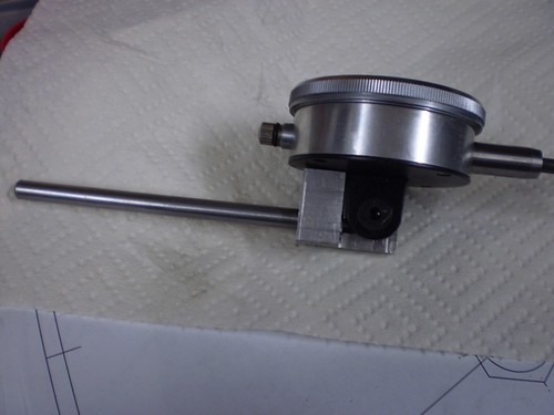
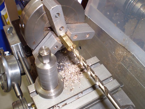
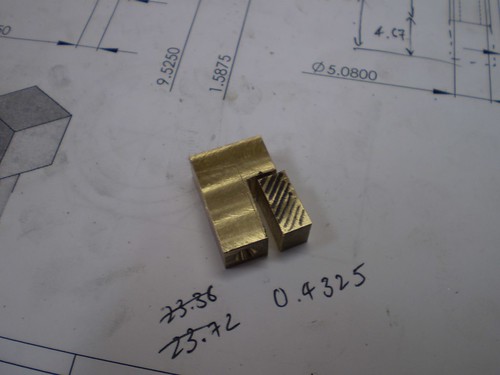
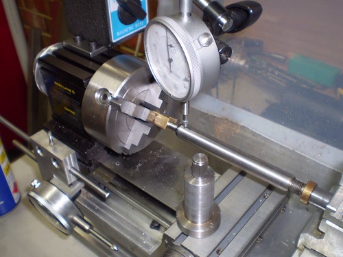
As can be seen in this shot, my Taig lathe has a dial gauge mounted under the headstock that I use to measure carriage travel. The mounting block also includes provision for a stop rod. A web surfer asked me recently to post some more detailed photos of the mounting.


P9200003


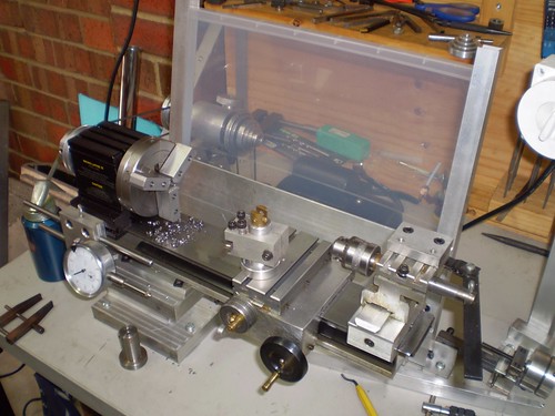
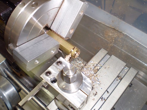
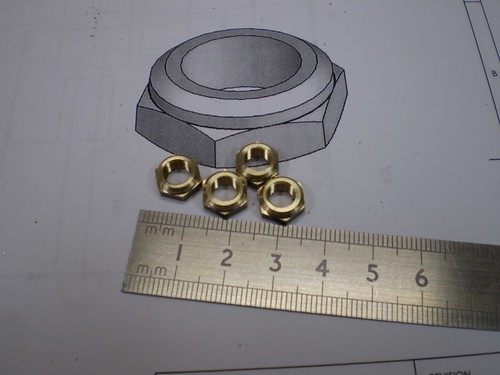
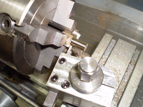
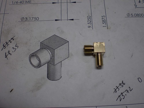
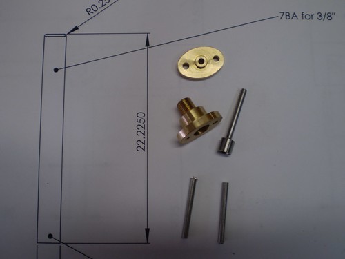
The block itself is L-shaped. The two cap screws pass through and into the T-slots in the headstock. The thumbscrew was the one that came with the lathe. It holds the stop rod (a piece of 0.250 silver steel/drill rod) in place with the aid of a brass pad.
P4190038


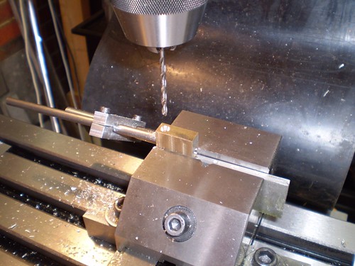
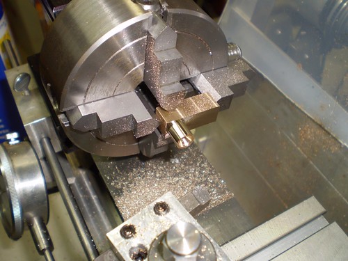
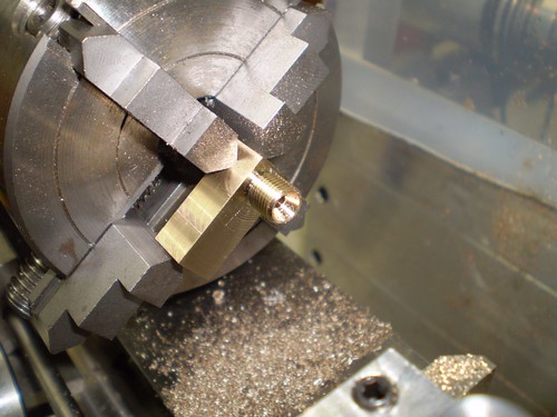
The dial gauge is mounted on a rod which passes through the hole pictured below. A clamping mechanism is devised from a slot and another cap screw.
P4190039


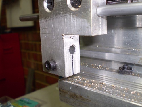
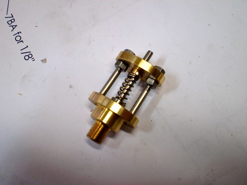
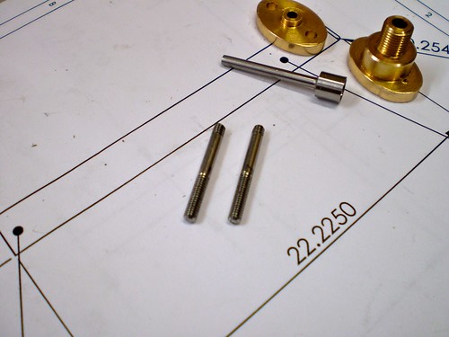
Here is the mount for the dial gauge. The rod is held on the block via a grub (set) screw, and the dial is mounted via another cap screw.
P4190037

Boiler Fittings: Firebox Door

I plan to use a butane burner in this boiler. One of the common ways to light these is to turn on the gas and put the match at the top of the chimney and hope you retain most of your eyebrows and that the resultant pop-back does not extinguish the burner. I was looking for a better way so I thought why not a door?


Since it will be painted, I am making it out of aluminium. Here is a shot on the mill whilst cutting the 1.5" radius so that it fits the boiler shell.


P1040008


Here is is transferred to the small mill to cut all the bits that don't look like a firebox door.


P1040009


Here we have just finished cutting out the centre and the two bosses that will be the top and bottom hinges.


P1040012

Monday 11 January 2010

Boiler Fittings: Lock Nuts

The lock nuts allow the boiler fittings to be positioned with more control. They are designed to lock against the boiler bushing. They are made out of 3/8" hex brass stock, and are a bit of an exercise in small scale production lathe work.


http://farm2.static.flickr.com/1299/5189173790_56afec23bf.jpg


Start by chucking up and drilling for the tapping size, in this case for 1/4"-40ME.


http://farm2.static.flickr.com/1292/5188573079_c4853d69a5.jpg


Now tap - I did start tapping with the tap held in the tailstock chuck and with the tailstock free to slide along the bed. This allowed me to start off square and straight. Once I had good engagement, I swapped for the tap holder to complete the job.


http://farm5.static.flickr.com/4089/5188573361_29676c8d94.jpg


Pictured below is the final step in 3. Step one - turn to 3/8" diameter for 1/16". Step two - chamfer at 45 degrees to approx 1/32" and then Step three - part to length.


http://farm5.static.flickr.com/4083/5189174464_63b0021f99.jpg


Lather, rinse and repeat (4 times) and we come to the finished article.
http://farm5.static.flickr.com/4108/5188573797_bf35f4ea9c.jpg

Boiler Fittings: Steam Outlet

The steam outlet is a fitting at the top of the boiler that provides a threaded attachment for the main steam line. It is made of brass; of which we start with a small block on the mill drilling the passages out.


http://farm5.static.flickr.com/4087/5189181950_8b3b574c8e.jpg


Once that is done we cut out a small bit of waste to make our lives easier when we mount in the lathe.


http://farm5.static.flickr.com/4092/5188581007_3642b50755.jpg


Using a spring loaded wobbler (actually it is the Taig live center, but it does double duty here) center the part so that the first boss can be turned.


http://farm5.static.flickr.com/4009/5188581271_f674b46d65.jpg


Turning complete now we have to thread 5/16-32 ME - a common size for commercially available nuts and tails.


http://farm5.static.flickr.com/4132/5188581519_a31922e960.jpg


Threading complete. I also turned a small semicircular groove where the boss meets the square section and chamfered the end.


http://farm5.static.flickr.com/4084/5189182918_c21a6cea5a.jpg


Here is a shot taken whilst turning the groove on the other boss. This boss is at 90 degrees to the other one and is smaller - in this case 0.250".


http://farm2.static.flickr.com/1030/5189183196_c278caed2d.jpg


This boss gets threaded 1/4-40ME and chamfered as well. Note the piece of soft aluminium protective packing between the chuck jaw and the part.


http://farm5.static.flickr.com/4127/5188582337_0958be0271.jpg


The finished article.


http://farm5.static.flickr.com/4104/5188582581_255e73c109.jpg

Saturday 9 January 2010

Boiler Fittings: Steam Saftey Valve

The boiler I am making requires a safety valve to bleed excess pressure from the boiler during operation. I am using the same design as the last boiler I made. It consists of a body and a bridge, both made from bronze and a stainless steel pintle that uses a spring to hold a stainless ball against a seat in the body. A pair of stainless rods hold the bridge above the body.


A picture tells a thousand words so here is the finished article:


http://farm5.static.flickr.com/4144/5189193382_ed6c7bbbdc.jpg


The body and bridge were both turned on the lathe and then shaped using the CNC mill. Here is a video of this process on the body.


Now we can make a start on the two stainless steel rods that hold the bridge up. Here they are cut roughly to length. The observant amongst you may notice the stupid 22.2250mm dimension which is simply a result of printing out metric drawings originally dimensioned in imperial.
http://farm5.static.flickr.com/4132/5188591491_4a28fe6b94.jpg
To get the rods to length they are faced in the lathe. I also take to opportunity to knock the sharp edges off as well.

http://farm2.static.flickr.com/1280/5188591693_41017697c1.jpg
I changed the headstock chuck over to a small Jacobs chuck which will hold the rod much more firmly than the normal 3 jaw turning chuck. I will thread the rods from both ends 7BA using a tail-stock die holder.

http://farm2.static.flickr.com/1267/5188591953_dfef85c668.jpg
Here are are the finished rods.

http://farm2.static.flickr.com/1386/5189193168_89838318cf.jpg