Saturday 26 May 2007

Project - Mine Engine Part I

Another engine - again a design from Elmer. This time the Mine Engine.


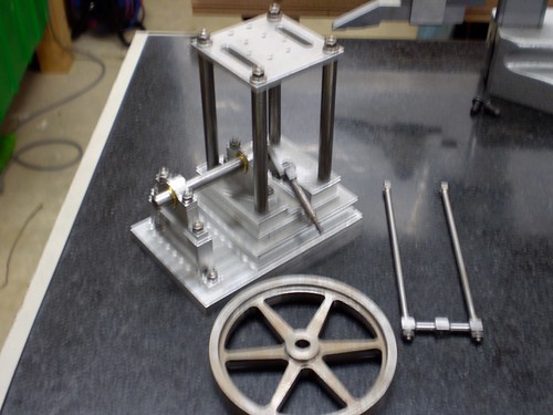
Shot showing Base, Main Bearings, Crankshaft, Flywheel, Columns and Table


http://farm6.static.flickr.com/5253/5541865159_39e3d574aa.jpg


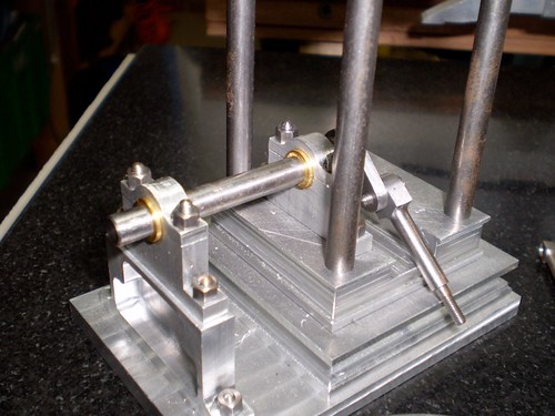
Close up of Main Bearings and the bearing pedestal. Both parts were machined on the CNC Mill.


http://farm6.static.flickr.com/5257/5542445728_6bc5d24aa2.jpg


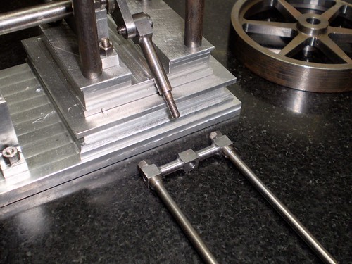
Closeup showing Connecting Rod


http://farm6.static.flickr.com/5291/5541865645_1f4609ecbd.jpg

Friday 20 April 2007

Project - Mine Engine Part II

Part II - The Cylinder.


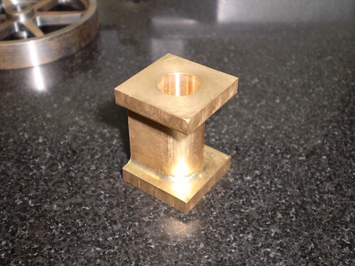
The Cylinder is a block of brass 25mm square by 35mm long. It has already been bored for the piston and the CNC Mill has been used to shape the outside.

http://farm6.static.flickr.com/5135/5541869469_5756b0099b.jpg


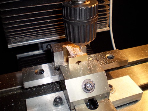
In this set-up the cylinder port face has the steam and exhaust ports milled and the holes for the studs that hold the steam chest on have been center drilled.

http://farm6.static.flickr.com/5132/5542450060_d47131903d.jpg


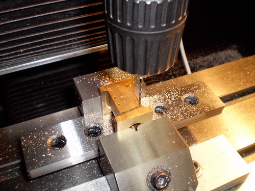
The steam chest stud holes are now being drilled.

http://farm6.static.flickr.com/5258/5542450322_9865e60571.jpg


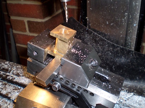
In this setup on the X3 Mill the steam ports are being drilled at a 15 degree angle. The sin vice is being used to hold the job.

http://farm6.static.flickr.com/5295/5541870395_3214b4c954.jpg


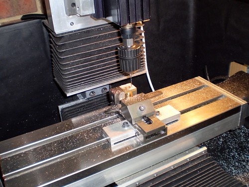
Wide shot - in this setup the end holes for the cylinder cover studs are being drilled.

http://farm6.static.flickr.com/5095/5542450892_9c79598d19.jpg