Research and Ponderings
I have been looking at getting a CNC capability for some time. I want it mostly to carve 'castings' from solid billets as my main interest is in building small engines. Here in Oz it is cheaper for me to buy (or build) a CNC machine and carve from the solid, than to order castings from the US or UK. If you want to do something a little out of the ordinary, like make your own patterns and get them cast yourself. Forget it. If you can first find somebody who will do the castings, you will then find you can't afford it.
Build, Retrofit or Buy
I considered retrofitting my Taig, however, the thought of carving out a bedplate in cast iron on the Taig filled me with creeping horrors. In addition CV 3D contouring with the Taig lead screws would be a problem because of backlash. I also thought about retrofitting my X3 and doing a ballscrew conversion at the same time. Then I saw www.5bears.com and I got inspired so I decided to build my own. I looked at lots of desktop machines and decided like Swede, that if I wanted the rigidity and performance, I would have to build because I couldn't afford to buy.
I wanted a machine of similar envelope to the Taig. ie X axis 300mm, Y axis 150mm, Z axis 230mm (12, 6, 9 inches respectively for our American friends) and a rotary axis. I wanted zero backlash on all four axes, I wanted massive and rigid, as it is a requirement to machine ferrous metals.
On the topic of eBay
If you live in the US, I'd imagine that eBay is a boon for projects like these. I however, do not live in the US so after looking at eBay for a while, I decided that whilst it could be taken advantage of for some things, it would be better if I looked elsewhere for parts, especially motion control.
For example, there has been a dearth of suitable ballscrews on eBay and premium prices are being paid for quite ordinary units. I figured finally that if I was going to spend AUD$200 on a ballscrew and AUD$50 freight to get it here, I may as well spend AUD$300 locally and get local after sales support and a warranty.
Similarly for linear guides. The freight costs to this part of the world are murder, and there never seem to be the right ones available. In addition, lately the prices have skyrocketted. Probably because of people like Swede telling everybody to go to eBay! :-)
I did however use eBay for a few things, like bBearings - 7200B angular contact bearings - for the ballscrews. I also picked up a harmonic drive to use as a 4th axis.
Basic Design Requirements
Massive and rigid |
It is a requirement that I machine ferrous metals, the vibration frequencies when machining these materials is quite low and thus the machine has to be as rigid as possible and structures such that it can damp unwanted vibration.
This sort of rules out a moving gantry design.
I had considered something like:

Which is a fixed table (disregard the 4th/5th axes) in a box design, however since cast iron was the material of choice, I would need a lot to construct a frame big enough and I'd never be able to lift it once constructed.
Another design is the fixed bridge design:

This has merits, however, I was not convinced I could get enough travel in the Z-axis whilst maintaining rigidity.
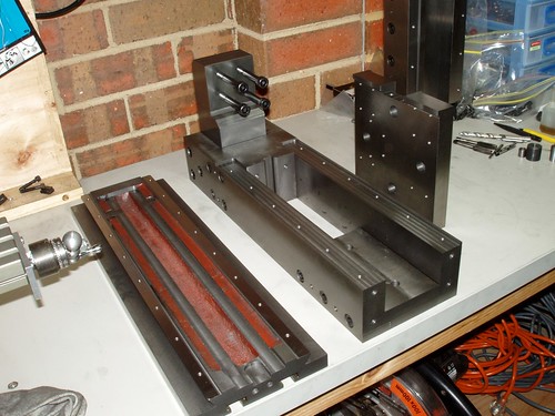
I settled on a C-Frame design thus:

The difference between this design and mine is the large carriage. My design uses a small carriage to reduce the torque requirement for all that mass. I could also contruct in such a way as to make everything adjustable (see accuracy below) and I could lift each piece when dissassembled.
Here's a picture:

|
Accuracy |
Whoa - here is a can of worms. I'm using ballscrews aren't I? 'Course it'll be accurate!
Wrong. Well at least not necessarily correct depending...After a lot of reading the secret appears to be something like this:
Design for repeatability. Accuracy can be achieved through calibration or compensation.
What this means is that since machine tools are deterministic and their errors display cause and effect relationships, if I can build compensation into my design I can make my machine tool accurate based on an observation and correction cycle; ie I can calibrate it.
Thus my final accuracy is not necessarily dependent on the accuracy of the components or my ability to accurately machine.
We'll see how this plays out....
|
Coolant |
The ability for this machine to be enclosed and doused liberally with flood coolant during operation is mandatory. I don't want it to be an afterthought. This means protection for all the motion gear and motors, and probably some sort of enclosure so coolant doesn't end up everywhere. |
Basic Design Walkthrough
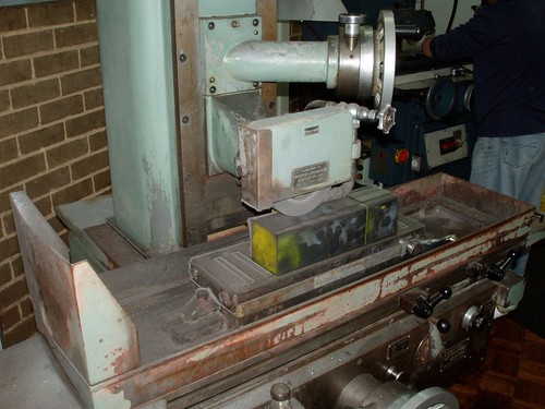
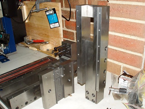
Bed and column - Structural members |

I chose cast iron for all structural parts of the machine. Cast iron is a good machine tool material.
The material I am using is 4E gray iron that is continuous cast in various sizes.
I got it from Flocast Australia (www.flocast.com.au). The people there were very helpful given I ordered such a small lot of material.
The weight of my order was approximately 90 kilograms (198lbs), the CAD software reckons that the machine will weigh about this after all machining. Bear in mind that this machine is only slightly larger that a Taig or chinese Mini-Mill.
The pictures show the two major assemblies, the bed and column. All mating surfaces will be ground, then will be permanently assembled using Loctite and dowels and then final machined as an assembly.
|
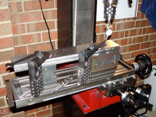
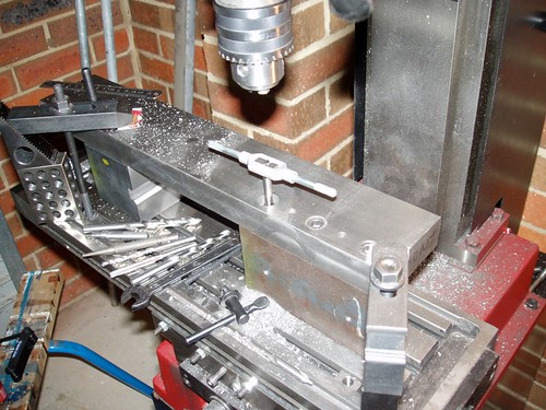
Ways |
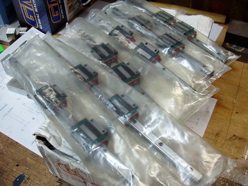
For the ways, I am using linear guides. I tried eBay, but I ended up with these from a local supplier, at a landed cost similar to what I would have paid on eBay after freight. The good bit about getting them locally is that I know exactly what I am getting and can spec exactly what I want. I also get the after sales service and warranty.
These particular linear guides are HiWin HG series rails and blocks in 15mm sizes. HG series blocks are a 4 row system that can take equal load in all four directions. 15mm rails are plenty big enough for this application. There is no chance of exceeding any of the static load ratings of these rails.
In addition these rails are a medium preload, so to move by hand they are a little stiff. This will help rigidity when machining harder materials.
I got these from Bearings Incorporated (www.bearingsinc.com.au) Neil Day is the guy to speak to - their service is excellent.
|
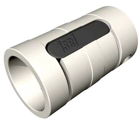
Ballscrews |
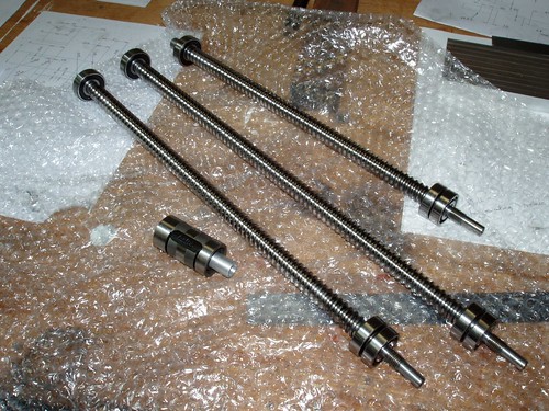
Rolled or ground? How much do you want to pay? These suckers are very expensive in ground form. Hence a trip to eBay, however I couldn't find any screws to suit (16mm diameter, 5mm pitch, correct length) so I again went on the hunt locally.
I ended up with ISEL rolled screws. These are class 7 screws (0.003"/12"). Doh! Dude your accuracy is gonna suck!
Not necessarily so - though if anybody wants to donate some class 0 screws to this project feel free.
Remember above all things this: The lead error in a ballscrew is a cumulative error over the stated length. The reality with rolled ballscrews is that over short lengths the actual absolute lead error is much smaller than this. ie you may travel any given 12" of a ballscrew and not get 0.003" error but if you travel 36" you may have anything up to 0.009" error ie it takes a longer travel before the error accumulates enough to be significant.
In any case we are not relying on the ballscrews for their accuracy, only their repeatability. If they are repeatable (which they are) we can compensate for lead error.
This is what manufacturers do in big machines anyway, the machine is mapped by calibrating it with a laser. When the software is asked to move an axis to a particular position, this position is compensated for based on requested vs actual motion when the calibration is done.
Backlash in these screws is not a concern because ISEL nuts can be squeezed slightly to preload them.
I got these screws from Applied Automation and Engineering (www.appliedauto.com.au). The guy to speak to is Andrew Shaw - again excellent service and support from a local company.
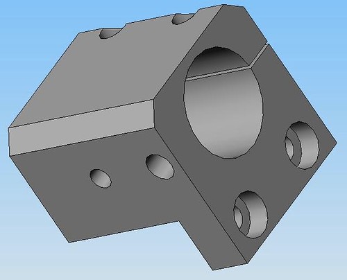
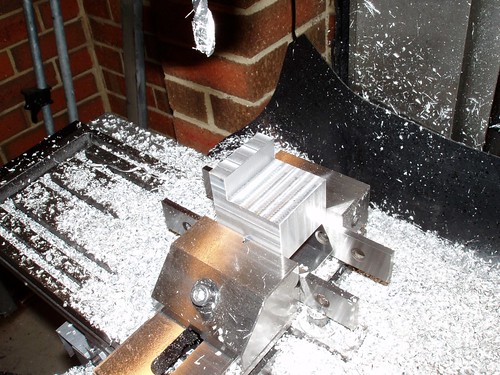
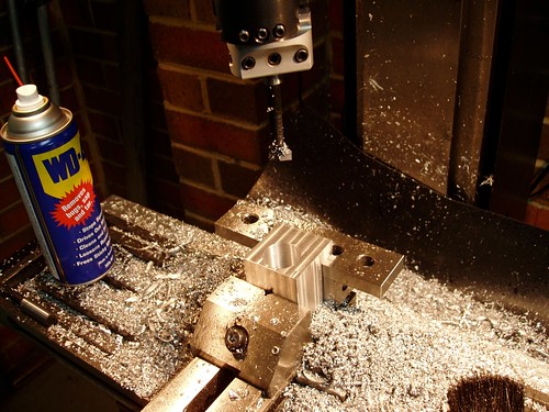
Another important part of the motion chain in a CNC machine is bearings for the ballscrews. The captive end of the screw needs to be held by a preloaded bearing such that there is no axial play.
In order to do this I am using angular contact bearings in machined housings. These bearings will be squeezed together in their housing to preload them.
|
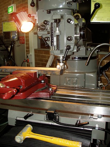
Table |
I took Swede's lead here and bought the same table that he used on his mill. The surface is excellent, and the cast iron is good quality. |
Controller and Drives |
I have chosen a stepper system. I wanted to get a servo system, but I blew most of my budget on motion hardware.
In addition, the type of machining that I envisage doing with this machine will dictate slower feedrates anyway so a stepper system will be not that much of a compromise.
The steppers are 300oz-in NEMA23 units and the controller is a 10x microstepping 4 axis controller with external power supply.
Since first time around I didn't want to muck about with electronics and I was after something turnkey - the stuff from www.lowcostcncretrofits.com fits the bill nicely - again a company with excellent service.
|
4th Axis |
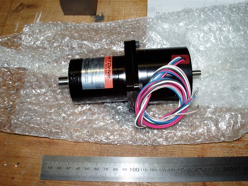
A Harmonic Drive 50:1 zero-backlash gearhead will be the heart of the rotary axis.
Got this on eBay for US$105.00 - Bargain.
The motor is a NEMA23 stepper. I haven't finalized the design of this part yet.
|