Tuesday 29 September 2009

Mounting a DRO on the 6x26 Mill

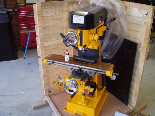
I kept the chinese DRO scales and readout display from the previous mill. All of the travels were able to accommodate the travels on the new machine. Having a DRO is something I don't think I could now live without.


Here are some photos showing what I did:


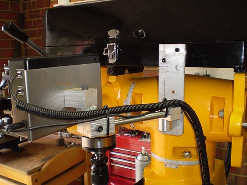
I drilled and tapped a couple of M5 holes in the bottom half of the belt guard - this allowed me to attach the readout unit to the side of the machine.
http://farm6.static.flickr.com/5087/5345612576_15df7999d8.jpg


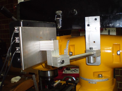
I removed the scale and the stop post that was attached to the front of the table and used the t-nuts that where in the t-slot at the front of the table to attach the X-axis scale. I used some lightweight aluminium angle to protect the scale from chips and coolant etc. The cable was put inside plastic sheathing and was tied down with cable ties.
http://farm6.static.flickr.com/5089/5345613240_f70c1bd79f.jpg


The Y-axis scale was attached to a plate that was attached in turn to the Y-axis stops bracket via standoffs. I used stand offs to clear the oiler for the knee dovetail. I replaced the steel stop piece with a new part that acts as both a stop and a bracket for moving the scale.
http://farm6.static.flickr.com/5169/5345002043_25ca35f759.jpg


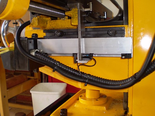
The Z-axis was the only place (aside from the readout bracket) that I had to drill holes to attach the scales. I have not covered these scales yet.
http://farm6.static.flickr.com/5210/5345612954_ac988c8d34.jpg


All the cabling was neatly routed and tied down with cable ties.


http://farm6.static.flickr.com/5124/5345002315_ee663b33fc.jpg

Tuesday 15 September 2009

A Countershaft for a Taig Lathe

I have been doing a bit of steel turning on the Taig lately again and have been having trouble parting off and form turning. I needed to slow the spindle speed right down. I didn't want to go and spend more money on a DC variable speed drive, plus I don't think they have enough torque at low speeds, so I decided to keep my trusty induction motor. I needed a countershaft.


I wanted a compact design that allowed me to adjust the belt tension easily in both directions and also allowed for quick changes of speeds. I sketched something up.


As you can see from the design, the countershaft is mounted on a pivoting arm that pivots around the same axis as the motor shaft. In this way I can adjust the tension between the motor pulley and the countershaft without disturbing the tension between the lathe and the countershaft. Similarly the tension between the lathe and the countershaft can be adjusted without disturbing the other belt. I also ended up with an assembly that was very compact.


CountershaftDesign.jpg


I started to turn sketch into metal.


http://farm6.static.flickr.com/5165/5345017233_ff08d6e9bf.jpg


Here you can see the two cheek plates and the pivot arm. The ball bearing are old Taig spindle bearings - bit worn but OK for this job. Here is a shot from the other direction:


http://farm6.static.flickr.com/5208/5345017531_15e12779fb.jpg


Here is the finished article:


http://farm6.static.flickr.com/5209/5345629156_6cd0a71038.jpg


And another close up:


http://farm6.static.flickr.com/5088/5345018153_c7121844d4.jpg

Tuesday 1 September 2009

New Machinery Day!!

It is New Machinery Day!!


I have decided it is time to go bigger - no not like that, I mean upgrade to bigger machinery. To this end my  7x14 minilathe and my X3 mill have been sold on eBay. I got good prices for both so I am pretty happy with the results - they both went to good homes.


I have replaced them with a 250mmx550mm (10x22 to our American cousins) lathe and a 6x26 knee mill. I got these from a local dealer - if you live in Melbourne you can do worse than Standaco in Nunawading.


The crane truck arrived this morning with my goodies on the back. Beautiful day - check out the sky.


http://farm6.static.flickr.com/5081/5345638420_2a10b1bd9f.jpg


Down comes the lathe...


http://farm6.static.flickr.com/5081/5345027205_c8718194e6.jpg


It was much easier than I thought it would be - he basically used the crane jib to lower them straight under the roller door.


http://farm6.static.flickr.com/5005/5345027555_d5b9aae89e.jpg


My shop now full of crates to unpack - mill in front, lathe in the middle and their respective stands at the back.


http://farm6.static.flickr.com/5045/5345027885_f29fc9ff37.jpg


Couldn't resist a small peek before going in to work; the new mill sitting in its crate.


http://farm6.static.flickr.com/5127/5345028207_93155aa7a9.jpg