Monday 20 March 2006

Project - CNC Mill Full Trial Assembly

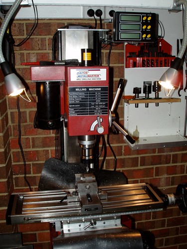
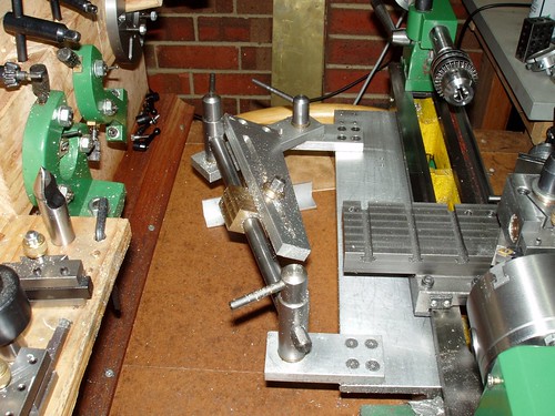
This is the full trial assembly of the mill to date. A few things to note:


  • I still have machining to do, for example the holes for mounting the swarf guarding and limit switches need to be drilled and tapped. I need to disassemble to perform this machining because I don't want cast iron dust in the linear guides or ballscrews.


  • I intend to paint all the bare cast iron, as you can see from some of the shots on this page, there is already a red tinge to some of the parts.


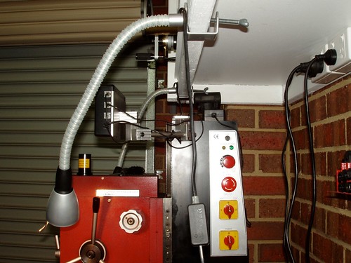
  • The motors are all wired in to the controller and everything moves - I have not done much in the way of tuning yet (I will post a video as soon as I have one)


  • I have also done no serious work on alignment or testing accuracy I will do this on final assembly


Here is the current the progress shot. You can see:


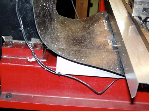
  • The plates for mounting the swarf guarding in the process of being cut


  • The GoreTex swarf guarding itself sitting on the table


  • The motors are all connected and working


200907232118.jpg


My #1 helper giving directions :-)


200907232118.jpg


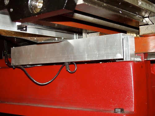
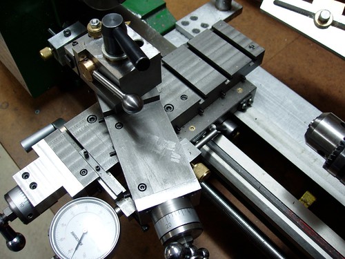
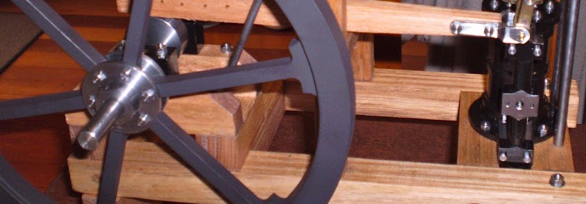
Close-up of X/Y carriage plate showing motor/bearing arrangement


200907232117.jpg


Another close-up showing X and Y motor mounts.


200907232117.jpg


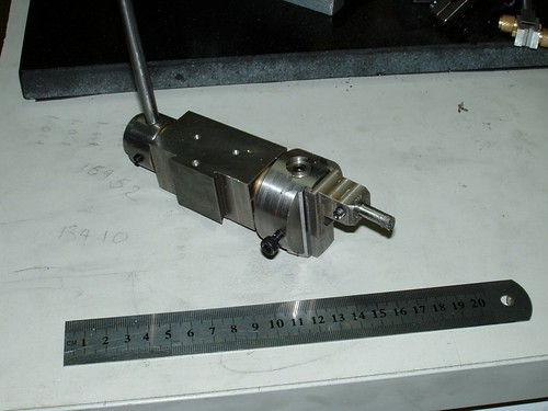
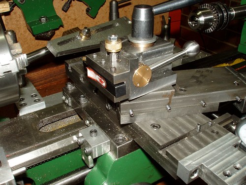
Close-up of Z axis spindle mounting plate. You can see the red tinge blooming even after brushing on a coat of oil every so often. Fresh ground cast iron and oxygen don't mix.


200907232116.jpg

Sunday 19 March 2006

Project - Ball Turning Tool

A bit like a boring head, this ball turner goes in the QCTP on the lathe.


http://farm6.static.flickr.com/5139/5541856287_e5cbdd2e76.jpg

Saturday 18 March 2006

Seig X3 Mill Evolutions

Some updated pics of my Sieg X3 Mill.


Front view showing DRO mounted and neoprene rubber swarf guarding. I bought the DRO to do the CNC Mill project - once you are used to using a DRO you never want to go back.


http://farm6.static.flickr.com/5096/5541849215_069e710489.jpg


Side view showing mount for DRO readout.


http://farm6.static.flickr.com/5013/5541849533_16eb3b13ec.jpg


Under the table view showing swarf shields for X and Y axis scales.


http://farm6.static.flickr.com/5179/5541848915_ba4c4cf1b8.jpg


Rear view showing swarf guards. You can also see the shims used to bring the column into truth.


http://farm6.static.flickr.com/5057/5541848631_0b478b3c44.jpg


7x14 MiniLathe Evolutions

....(or "from a sow's ear comes a silk purse...")


Picture from the rear showing:


  • The taper attachment - the bronze block rides on the shaft and the slotted plate is attached to the crossslide. The screw feed on the crossslide is disengaged and as the carriage moves so does the crossslide according to the angle set.

  • The cam-lock tailstock mod that I did

  • The 3 T-slots at the rear of the new crosslide


http://farm6.static.flickr.com/5131/5541844117_73401f52dd.jpg


Top view of the new crossslide showing:


    T-Slots
  • New compound slide

  • the lever (between the bed shears) for the cam carriage lock

  • The dial indicator attachement for reading out crossslide travel

  • Quick Change tool post

  • Carriage stop


http://farm6.static.flickr.com/5291/5541844403_6060e52c07.jpg


View from the other side showing tool holder for QCTP.


http://farm6.static.flickr.com/5134/5542424912_671ff79fb6.jpg

Friday 10 March 2006

Project - Offset Boring Head

This is an offset boring head (half finished). It is 1 1/2 inches in diameter and made of steel. It has a 3/4-16 thread and register to fit the Taig spindle, and a 40 TPI feed screw.
I still need to drill and bore the bottom half for the boring bits and graduate the feed screw dial.


You can see a screw missing from the keep plate on the front - I broke a tap behind the hole and have since repaired it by grinding and driving out the remains of the tap and plugging the hole with a piece of stock press fit into the body. This will be drilled and tapped later on.


http://farm6.static.flickr.com/5177/5541854289_2f1662e5f0.jpg